Wednesday, 15 October 2014

What is Unity?

Hey everyone welcome back to another blog written by the angry game dev girl! WHOOOOH! Ok so today I will be discussing Unity, ( No I'm not talking about the type of Unity with it's togetherness that most people are familiar with I'm talking about the game engine Unity). Now Unity, created by (the wonderful company) Unity Technologies, is a multi-platform game creation system that  includes a ready to go game engine and an integrated development environment. Originally Unity was primarily developed for Mac OS however it now supports over 15 different platforms and is also the default software development kit for the Nintendo Wii U.


Overview:

Unity's slogan is Create. Connect. Succeed is completely accurate considering this system is created to allow developers the ability to almost effortlessly create and build successful prototypes and games through its multi-platform and interactive content capabilities. It's ability to target games to multiple platforms is one of things Unity is most notable for. While developing, game creators have complete control over building for mobile devices, web browsers, desktops and consoles. Currently there are two versions of Unity, Unity Pro, which is available for a fee and used in high commercial uses, and Unity Free, which is a free to use software used for noncommercial and low-end use.

Supported Platforms:


Currently Unity supports over 15 different platforms which allows developers to easily transition between platforms with little to no changes to the game. The following are the most notable supported platforms:
  • IOS & Mac
  • Android
  • Windows, Windows Store Apps  & Windows Mobile
  • Blackberry
  • Web Browser
  • Oculus Rift
  • PS3, PS4, PSVITA, & Playstation Mobile
  • XBox & Xbox One
  • Wii U
While Unity was originally developed for IOS and MAC OS use it has grown to support so many different platforms, most notable being Nintendo's Wii U, given that is included as a part of the standard development kit for that console. 

Features:

The main thing that separates Unity from other game engines is not only its multi-platform capabilities and its user friendly interface but also the numerous features that it provides its users in order to provide such usability. The following lists some of Unity's key features and what these features include:
  • The Rendering System:
    • This system allows for developers to easily implement lighting, lightmapping, which uses the Beast Lightmapping engine, Screen Space Ambient Occlusion, Shaders, post-processing, Substances, Graphics API Support, among others.
  • Physics:
    • Unity's Physics engine utilizes the NVIDIA PhysX physics engine in order to allow developers the ability to do physics on cloth, soft and rigid-body interactions, ragdolls, joint systems and wheel collision.
  • Terrain:
    •  This features allows for terrain painting, detail texture painting and tree creation.
  • Networking:
    •   Unity includes features such as state synchronization, real-time networking, remote procedure calls, backend connectivity, web integration and massive multiplayer online in order to allow for the facilitation of standard multiplayer games.
  •  Audio:
    •  The inclusion of one of the most used sound engines, FMOD, allows for easy addition of sounds and music. This features includes the ability to live preview, curve-based sound attenuation editing and audio filter support.
  • Preview Functionality:
    •  This feature allows developers to quickly test features and mechanics of their games in order to check that everything is in working order.
  •  Scripting:
    • Unity allows developers to create specialized scripts using JavaScript, C# and Boo in order to create unique features and add in artificial intelligence to NPCs.

  •  Development & Editor Tools:
     
     
    • Unity supports Debugger integration, profiling, particles, Animation, Shaders, Visual Scripting, UV Unwrapping, Beast lightmap baking, Pathfinding, External Package and TrueType font support in order to allow easy development and editing.
  • Asset Store:
    • Unity has a unique feature in its Asset Store which is a unified marketplace for acquiring additions to the engine as well as assets for use in development purposes either for free or for a fee.
  • Unity's Website:
    • The website for this game engine while not apart of the actual engine is a fantastic feature of Unity due to the multitude of tutorials and learning aids for developers and game makers to learn and develop their skills. 
All in all Unity is one of the best engines available for game makers to use as a means of prototyping and actual game creation.

In case anyone is interested in learning more about Unity and how to use it check out the link below:


Thursday, 25 September 2014

Game Engine Overview


Welcome back everyone to another wonderful installment of blogs done by the Angry Game Dev Girl (Holds for applause *crickets* ..... OK then). Well if you can't already tell this new exciting round of blogs are going to be focused on Game Engines as required by my Game Engines class (kinda self-explanatory but whatever). Now for this class there will a series of 5 blogs, the first of which will cover a brief overview of what a game engine is, discuss briefly how it works and briefly talk about some of the available engines and what they are used for in the industry. The others will probably be an in depth analysis and comparison between 2 or 3 engines, unless we learn about something super, super cool and I just absolutely have to write a blog about it. Now with out further ado let us begin our adventure in the world of Game Engines (please note I am not a very good programmer so if any technical stuff is wrong I greatly apologize).

What is a Game Engine?


A game engine can be described as a software framework that is designed for the creation and development of a video game for consoles, mobile devices and PCs. This framework is an extremely important aspect of game development because without proper functionality in the engine a game will not be able to include many of its features or run efficiently and effectively.  A Game Engine is the software whose main functionality and algorithms are solely responsible for the game's mechanics however it is not the rendering engine. There can be numerous engines, which are referred to as middleware, that make up the main game engine. These other components can include your physics engine, and your rendering engine, among others.

Functionality in a Game Engine

 In order to create a game engine you need to include some core functionality in order to do the things you want to do in your game. Having your engine's core functionality in your engine designed specifically for your game needs is extremely important because you don't want a general functionality in your engine that requires you to do a ton of extra work to get what you want your engine to do, simply build in the functionality you need into your engine so that your engine works the way you need it. There are a few typically core functionalities that are usually found in an engine:

  • Rendering Engine (the renderer) for 2D/3D graphics
  • Physics Engine for gravity, collision detection/response, etc.
  • Sound for Game audio
  • Scripting for quick editing to
  • Animation for cut scenes, effects, etc.
  • Artificial Intelligence (AI/NPCs) for intractable characters, enemies, etc.
  • Networking for multiplayer mode, online mode, etc.
  • Streaming for changing code on the fly and instant changes
  • Memory Management for saving memory, preventing memory leaks, etc.
  • Threading for using multiple threads for multitasking on the CPU
  • Localization Support for for localized language support
  • Scene Graph for vector-based graphic editing

Purpose of a Game Engine

 A game engine is a development tool that allows for simplified, rapid game development that provides many of the elements a game developer would need to build their game. The purpose of an engine is to facilitate easy development by providing the functionality of graphics, sound, physics, and AI among others. A well built game engine not only allows for fast and easy production but also provides a flexible and reusable software platform that reduces the cost, complexities and time-to-market during development. Game Engines can also be used to port the same game to run across multiple platforms such as consoles and PCs, with very few changes to the original source code. By using a component based architecture, engines are able to replace or extend its systems to have more specialized game components.

How does it work?

As mentioned earlier in this and as the above image shows, a game engine is made up of numerous systems that are all linked together to provide a game's mechanics and functionality. Basically, a game engine is an component system built out of mini systems/engines that are all linked together to create the mechanics and functionality of a game. All of these mini systems are simply components or extensions of the larger systems that have specific jobs to do that allows the larger system to create an interface for developers to make a game, by allowing them to instruct the engine (the larger system) to do something using scripting, c++, etc.

If you think about an engine like a spider, the larger system (the engine) is the spider itself, while the mini systems (the component engines like the graphics, physics, etc engines) are the spiders legs. The spider needs all its legs to properly function and perform its tasks and if it is missing a leg or one leg isn't working the spider cannot fully perform its tasks to its full abilities. The same is said when talking about a game engine, should one of its components is missing or not working correctly then the engine will not function properly nor will it be able to perform its task properly.  It is essentially a system dependent on its linked component systems to be able to provide the needed functionality to create a game.

Some Current Engines and Their Use in the Industry 

So there are numerous engines available currently in the gaming industry, some of the are free/open source while others are sold by companies for commercial use. Below I will briefly talk about a few that are available:

  • App Game Kit
    •  Platform: Android, iOS, Mac, PC
    • Used in: Cannon Ball, Jumping Jack, etc
  • BigWorld
    •  Platform: Browser, PC
    • Used in:World of Tanks, Realm of the Titans, etc
  •  BlitzTech
    •  Platform: 3DS, Android, iOS, Linux, Mac, PC, PS3, PS Vita, Wii, Wii U, Xbox 360
    • Used in:  Rayman Raving Rabbids, Kumo Lumo, etc
  • CryEngine 3
    •  Platform: Next-gen consoles, PC, PS3, Xbox 360
    • Used in:  Crysis, Aion, Sniper: Ghost Warrior 2, etc
  • GameBryo
    •  Platform: Android, iOS, PC, PS3, Wii, Wii U, Xbox 360
    • Used in: Catherine, Epic Mickey, etc
  • GameMaker
    •  Platform: Android, Browser, iOS, Mac, PC, Windows Phone
    • Used in:  Hotline Miami, Mr. Karoshi, etc
  • Havok Vision Engine
    •  Platform: Android, iOS, Linux, Mac, PC, PS3, PS Vita, Wii, Wii U, Windows Phone, Xbox 360
    • Used in:  Carnival Island, Soul Worker, etc
  • Infernal Engine
    •  Platform: 3DS, Android, iOS, Linux, Mac, PC, PS3, PS Vita, Wii U, Xbox 360
    • Used in:  The Walking Dead: Survival Instinct, etc
  • Marmalade
    •  Platform: Android, BlackBerry OS, iOS, Mac, PC, Smart TVs, Windows Phone
    • Used in: Call of Duty: Black Ops - Zombies, Cut the Rope, etc
  • Unity 4
    •  Platform: Android, Browser, Flash, iOS, Linux, Mac, PC, PS3, Wii U, Xbox 360
    • Used in: Castle Story, Wasteland 2, etc
  • Unreal Engine 3 & 4
    •  Platform: Consoles (TBA), PC, PS4
    • Used in:  Dishonored, Mass Effect, BioShock Infinite, etc
More Information: 

For anyone who  wants anymore information on Game Engine you can find more info with the links below:

Game Engines How do they work
What is a Game Engine?
Game Engines and How They Work
Game Engine Wiki
Open Source Game Development

Monday, 21 April 2014

Shadow Mapping + Tutorial

In my last two blogs I talked about a few different Mapping techniques and showed you how to achieve a few of them, now those mapping techniques are primarily used for the manipulation of geometry or the illusion of manipulation. In this blog I'm going to focus on Shadow Mapping, which is another type of mapping however this one is used in the creation and formation of shadows in a scene.


WHAT IS SHADOW MAPPING?


                                  No Shadow Mapping                            Shadow Mapping
 Shadow mapping, otherwise known as projective shadowing, is a 3D computer graphics process where shadows are added into 3D scenes. This concept was introduced in 1978 by Lance Williams, a prominent graphics researcher (You can find more info on him HERE),in his paper entitled "Casting Curved Shadows on Curved Surfaces".

In Shadow Mapping, Shadows are created testing whether a pixel is visible from the light source. This is done by comparing it to a z-buffer or depth image of the light source's view and then stored in the form of a texture.

Algorithm Overview:

When creating Shadow Mapping there are two major steps that are required in this algorithm. The first step produces the shadow map itself, and the second applies it to the scene. Depending on how you do your shadow mapping implementation, and how many lights that are in your scene, you may required multiple additional passes.


Step 1: Creating The Shadow Map


=> In the 1st step the scene is rendered from the light's point of view, which should be a perspective projection
=> In this step the depth buffer is extracted and saved, only the depth info is important at this step so avoid updating the colour buffers and disable all lighting and texture calculations
=> The depth map is stored as a texture

Step 2: Shading The Scene

=> In the 2nd step you draw the scene from the usual camera viewpoint and apply the shadow map
=> There are 3 major components in this step:
                    1. Find the coordinates of the objects as seen from the light
                    2. Test which compares that coordinates against the depth map
                    3. Draw the object in either in shadow or light

Step 3: Light Space Coordinates Test 

=> To test a point against the the depth map, its position in the scene coordinates must be transformed into its equivalent position as seen by the light. This is accomplished by Matrix Multiplication.
=> The object location in the scene is found with coordinate transformation, using a second set of coordinates created to find the object in light space.


Step 4: Depth Map Test
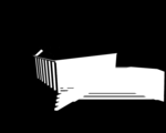
=> After finding the light-space coordinates are found, the x & y values = a location in the depth map, and the z value = depth can now be tested against the depth map.
=>If the z value > the valued stored in the depth at an (x,y) location the object is behind an occluding object and drawn in shadow.
=> If the (x,y) location is outside of the the depth map, the programmer decides whether or the surface is light or shadowed by default.

Step 5: Drawing The Scene

=> There are a few ways to draw the scene
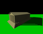
            1.  If Shaders are available, the depth map may be performed by a fragment shader which simply draws in shadow or light in a single pass.
            2. If Shaders are unavailable, implementation must be done through hardware extension (ex. GL_ARB_shadow) which does not allow the choice between being lit or shadowed and required more rendering passes.

More Info:

For more information about Shadow Mapping, here are a few links that will help:

SHADOW MAPPING TUTORIAL


In this section I will go over what is necessary in your GLSL Shadow Mapping shaders, now these shaders are done in version 330 and may not work in your code and should only be used as a guideline in your own code. Also note that this version of Shadow Mapping also has projected textures implemented as well.
                                                             No Shadow Mapping

Fragment Shader:


#version 330 core

in vertex
{
    vec3 positionObj;
    vec3 normalObj;

    vec2 texcoord;

    vec4 positionLt;
} data;

uniform vec3 eyePos;
uniform vec3 lightPos;
uniform sampler2D diffuseMap;
uniform sampler2D shadowMap;
uniform sampler2D projTex;//projective textures

layout (location=0) out vec4 fragColour;


vec3 PhongLighting(in vec3 fragPos, in vec3 fragNorm,
    in vec3 diffuseColour, in vec3 specularColour)
{
    // ...this is generally a dark constant
    const vec3 ambient = vec3(0.00, 0.00, 0.05);


    // diffuse component
    vec3 N = normalize(fragNorm);
    vec3 L = normalize(lightPos - fragPos);
    float Lambert = max(0.0, dot(L, N));


    // specular coefficient
    vec3 E = normalize(eyePos - fragPos);
    vec3 R = reflect(L, N);
    float Phong = max(0.0, dot(R, -E));
    // pro-tip: doing this is faster than calling the pow() function...
    Phong *= Phong; //^2
    Phong *= Phong; //^4
    Phong *= Phong;    //^8


    // add components
    vec3 diffuse = Lambert * diffuseColour;
    vec3 specular = Phong * specularColour;
    return ( diffuse + specular + ambient );
}


void main()
{
    //this is for projected textures
    vec3 projective = vec3(1.0);

    // 1) Perform clipping manually from point of view
    //so we can sample from the shadow map
    vec4 positionLtClip = data.positionLt;

    //perspective divide ------> normalize device coordinates
    vec4 positionLtNDC = positionLtClip / positionLtClip.w;

   
    //this is for debugging purposes to check if its working
    //it makes rainbow fog :D
    //fragColour = positionLtNDC;
    //return;

    // 2) clip test
    //if we go beyond these values it will skip over this
    //and just do regular lightinf instead of shadow mapping
    if ((positionLtNDC.x > -1) && (positionLtNDC.x < +1) &&
        (positionLtNDC.y > -1) && (positionLtNDC.y < +1) &&
        (positionLtNDC.z > -1) && (positionLtNDC.z < +1))
        {
        //test
            //fragColour = vec4(1.0);
            //return;
            // 3) serialize for screen space
            vec3 positionLtScreen = positionLtNDC.xyz *0.5 + 0.5;

            //test
            //fragColour.rgb = positionLtScreen;
            //return;

            vec2 shadowTexcoord = positionLtScreen.xy;
            float fragmentDepth = positionLtScreen.z;

            // 4) Shadow Test
            float shadowDepth = texture(shadowMap, shadowTexcoord).r;

            //test
            //fragColour = vec4(shadowDepth);
            //return;
            if (fragmentDepth > shadowDepth)
            {
                fragColour = vec4(0.0);
                return;
            }
            else

            projective = texture(projTex, shadowTexcoord).rgb;

        }

    vec3 diffuseColour = texture(diffuseMap, data.texcoord).rgb;
    const vec3 specularColour = vec3(1.0);

    fragColour.rgb = PhongLighting(data.positionObj, data.normalObj,
        diffuseColour, specularColour);
        fragColour.rgb *= projective;
}


Vertex Shader:

#version 330 core

layout (location=0) in vec4 position;
layout (location=2) in vec3 normal;
layout (location=8) in vec2 texcoord;

uniform mat4 MVP;
uniform mat4 lightMVP;

out vertex
{
    vec3 positionObj;
    vec3 normalObj;

    vec2 texcoord;

    vec4 positionLt;
} data;

void main()
{
    gl_Position = MVP * position;

    data.positionObj = position.xyz;
    data.normalObj = normal;
    data.texcoord = texcoord;

    data.positionLt = lightMVP * position;
}


Main.cpp:

These are few things to remember to include in your main.cpp file:

1. Edits to your FBO

        // FBO for the shadow pass
        const unsigned int useColour = 1;    // ******** change this later...
        shadowMapPass->Initialize(shadowMapSize, shadowMapSize, useColour, 1, 0);


2.  1st Pass: Shadow Pass in your Render Function

// PASS 1: SHADOW PASS
        // ******** (1)
                projectionMat = light0Proj;
        eyeToWorld =
            ObjectLookAt(&light0, light0.position,
                bmath::vec::v3y, bmath::vec::v3zero);
        UpdateCameraMatrices();
        light0ViewProj = viewProjectionMat;

        // proceed with drawing the objects
        shadowMapPass->Activate();
        glViewport(0,0,shadowMapSize,shadowMapSize);
        glClear(GL_COLOR_BUFFER_BIT | GL_DEPTH_BUFFER_BIT);

        shadowPass->Activate();


        // ******** (3A)
        glCullFace(GL_FRONT);

        DrawObjectShadowPass(&ground, cubeRenderable, 1,0,0);
        DrawOBJLoadedObjectShadowPass(&tower, towerOBJ, 0,1,0);
        DrawOBJLoadedObjectShadowPass(&gumbot, gumbotOBJ, 0,0,1);

       
        // ******** (3B)
        glCullFace(GL_BACK);


3. 2nd Pass: Scene Pass

// PASS 2: SCENE PASS
        // draw scene regularly


        // update camera once per-frame
        projectionMat = camera0Proj;
        eyeToWorld =
            ObjectLookAt(&camera0, camera0.position,
                bmath::vec::v3y, bmath::vec::v3zero);
        UpdateCameraMatrices();
       
       
        scenePass->Activate();
        glViewport(0,0,windowWidth,windowHeight);
        glClear(GL_COLOR_BUFFER_BIT|GL_DEPTH_BUFFER_BIT);
       
        PhongWithShadowMap->Activate();

       
        cbmini::cbfw::FrameBuffer::SetTextureInput(3);
        glBindTexture(GL_TEXTURE_2D, penguins);
        cbmini::cbfw::FrameBuffer::SetTextureInput(2);
        shadowMapPass->BindDepth();

       
        DrawObject(&ground, cubeRenderable, groundDM, 0);
        DrawOBJLoadedObject(&tower, towerOBJ, towerDM, 0);
        DrawOBJLoadedObject(&gumbot, gumbotOBJ, gumbotDM, 0);


4. 3rd Pass: Display Pass

    // PASS 3: DISPLAY PASS
        // just slap a texture on a plane!
        cbmini::cbfw::FrameBuffer::Deactivate();
        glDisable(GL_DEPTH_TEST);

        displayPass->Activate();
   
        cbmini::cbfw::FrameBuffer::SetTextureInput();

        // ******** (2)
        /*shadowMapPass*/scenePass->BindColour/*BindDepth*/();

        fsqPlane->ActivateAndRender();


                                                                 Shadow Mapping  
                    
                                                Shadow Mapping with Projected Texture

Sunday, 20 April 2014

Mapping Tutorial

So I know it's been a while since I last blogged and partly it is because I've been busy with my animation and Production class and also my parents were recently in a pretty bad car accident and have been needing my help with a lot of things around the house and sometimes even sitting up (which really cuts into homework, studying and Blogging time but you know that's life I guess). No in my last blog, which you can find Here, I talked about 4 different types of mapping. In this tutorial I'm going to show you how to create a simple Displacement map in Photoshop, as well as the shader (in version 120 since that's the only version I know how to write the shader for displacement mapping) and how to write the shader for normal mapping. In addition, I'll be showing how to get the different types of maps from a model you have manipulated and sculpted in Mudbox.

DISPLACEMENT MAPPING

When creating a displacement map in Photoshop the easiest way is to start by using an image of clouds. Now if your confused about the clouds I promise I will explain it so it all makes sense by the end of this blog.
An image like this works perfectly, in Photoshop there are 2 simple steps you have to do to create  a simple displacement map.

Step 1: Strip the colour out of the image
               => This can by down under the Image tab, under Adjustments, select the Black & White option. This is strip all colour out of the image.

Step 2: Save the image as Displacement1, them horizontally flip the image to get a second displacement map.
               =>This allows for you to switch between the images to demonstrate the displacement.
Example Maps
 Now these maps aren't going to do much good with having the shader to go with it. I will be showing you how to write the shader and list a few things that are important to do and have in your main. Just remember that I will be showing you how to write the displacement Map shader in version 120 since that's the way I know how to write it.

Fragment Shader:

#version 120

varying vec2 out_texcoord;
uniform sampler2D DisMap;

void main()
{
    gl_FragColor=  texture2D(DisMap, out_texcoord);
}


Vertex Shader:

#version 120

uniform sampler2D DisMap;
varying vec2 out_texcoord;

void main()
{
    out_texcoord = gl_MultiTexCoord0.st;
    float x=texture2D(DisMap, out_texcoord).r;
   
    vec4 newcoordinate = vec4(gl_Normal, 1.0) * x + gl_Vertex;
    gl_Position = gl_ModelViewProjectionMatrix * newcoordinate;
   

}


Now a few thing to remember to do and include in your main are the following (Now remember my code is set up differently than yours will be, these are just a few guidelines to keep in mind and depending on how you do your code you may need more or less of these suggestions):
  • Ensure you have your proper variables and handles necessary
    •  unsigned int disp_DisplacementMap; 
    • unsigned int DisplaceProgram;
    • unsigned int Displacement_tex;
    • unsigned int Displacement2_tex;
  •  Don't forget to bind you texture to your object
    • glBindTexture(GL_TEXTURE_2D, Displacement_tex);
  •  Don't forget to include your shader programs
    • const char *frag = "resource/shaders/Displacement_f.glsl";
    • const char *frag = "resource/shaders/Displacement_v.glsl";
  • Make sure to create a handle for the texture Uniform
    •      disp_DisplacementMap = glGetUniformLocation(DisplaceProgram, "DisMap");
  • Load your images properly 
    •   Displacement_tex = ilutGLLoadImage("resource/images/Displacement.png");
    • Displacement2_tex = ilutGLLoadImage("resource/images/Displacement2.png");
  • Make sure you set up your load projection and view matrices for the current viewer properly
    •     glUseProgram(DisplaceProgram);
         
          glUniform1i(disp_DisplacementMap, 1);
          glActiveTexture(GL_TEXTURE1);

          if (mode1)
          {
              glBindTexture(GL_TEXTURE_2D, Displacement_tex);
          }
          else if(!mode1)
          {
              glBindTexture(GL_TEXTURE_2D, Displacement2_tex);
          }

NORMAL MAPPING

 Now for Normal Mapping I will show you how to write the shader in version 330 (since that's the way I know how to write it best), then using Mudbox I will show you how to extract maps from you models.

Here is the normal mapping fragment and vertex shaders, these shaders are using per-fragment Phong Lighting in these shaders.

Fragment Shader:

/*
    Object-Space Normal Mapping with Phong Lighting FS

    GLSL fragment shader that performs per-fragment Phong Lighting.
    Also applies texture.
*/

#version 330 core

in vertex
{
    vec3 positionObj;
    vec3 normalObj;
    vec2 texcoordObj;
} data;

uniform vec3 eyePos;
uniform vec3 lightPos;
uniform sampler2D diffuseMap;

layout (location=0) out vec4 fragColour;


vec3 PhongLighting(in vec3 fragPos, in vec3 fragNorm,
    in vec3 diffuseColour, in vec3 specularColour)
{
    const float shininess = 10.0;


    // ...this is generally a dark constant
    const vec3 ambient = vec3(0.00, 0.00, 0.05);


    // diffuse component
    vec3 N = normalize(fragNorm);
    vec3 L = normalize(lightPos - fragPos);
    float Lambert = max(0.0, dot(L, N));


    // specular coefficient
    vec3 E = normalize(eyePos - fragPos);
    vec3 R = reflect(L, N);
    float Phong = max(0.0, dot(R, -E));
    Phong = pow(Phong, shininess);


    // add components
    vec3 diffuse = Lambert * diffuseColour;
    vec3 specular = Phong * specularColour;
    return ( diffuse + specular + ambient );
}

uniform sampler2D normalMap;

void main()
{
    vec3 diffuseColour = texture(diffuseMap, data.texcoordObj).rgb;
    const vec3 specularColour = vec3(1.0);

    vec3 normal = texture(normalMap, data.texcoordObj).rgb;
    normal = normal*2.0 - 1.0;

    //fragColour.rgb = PhongLighting(data.positionObj, data.normalObj, diffuseColour, specularColour);
   
    fragColour.rgb = PhongLighting(data.positionObj, normal, diffuseColour, specularColour);

    //fragColour.rgb = normal; //this is a preview only
}


Vertex Shader:

/*
    Pass Attributes VS

    GLSL vertex shader that performs the clip transformation and passes all
    relevant attributes down the pipeline.
*/

#version 330 core

layout (location=0) in vec4 position;
layout (location=2) in vec3 normal;
layout (location=8) in vec2 texcoord;

uniform mat4 mvp;

out vertex
{
    vec3 positionObj;
    vec3 normalObj;
    vec2 texcoordObj;
} data;

void main()
{
    // mandatory!
    gl_Position = mvp * position;

    // additional info
    data.positionObj = position.xyz;
    data.normalObj = normal;
    data.texcoordObj = texcoord;
}

HOW TO CREATE AND EXTRACT MAPS IN MUDBOX

In this section of the tutorial I will be focusing on how to create and extract few types of maps that can be used for a different techniques.

The first thing you want to do is load a model and manipulate the model (now if you already manipulated your model or have a higher res model you want to create these maps for well then you're golden).
So for my model I have a tree that I have carved and manipulated both the leaves and the trunk area and will be using this model to show you how to get the maps you need.

Step 1: Open the UV & MAPS Tab

Step 2: Select Extract Texture Maps, then choose New Operation


Step 3: Choose the Type of of Map


Step 4: Select Your Desired Options

Step 5: Extract Your Maps

Wednesday, 9 April 2014

Mapping

Oh man I feel like I have blogged in a while (which is probably extremely accurate since life has been so crazy busy). Well now I'm back and going to focus on different types of Mapping in this blog. I may also create another corresponding blog that will show you how to create certain maps and may even show you have to write the shader for one of the types of mapping.

Now Mapping is a type of computer graphics technique that allows you to create different effects by changing the aspects of a 3D model. There are a few different types of Mapping such as Displacement Mapping, Bump Mapping, Normal Mapping and Parallax Mapping.

DISPLACEMENT MAPPING

Displacement Mapping is a computer graphics technique that uses a texture, often referred to as a height map, that creates an effect where the position of the vertices of a model are displaced in order to create a change in the model's geometry and add geometric detail to the model surface. Essentially displacement mapping uses input from the info stored in a texture map to create bumps, creases, ridges, etc in the model's actual mesh. By actually deforming the mesh shadows can be created by the deformations, and can also occlude the other objects.
Additional Info:

BUMP MAPPING

Bump mapping like displacement mapping is a technique in computer graphics that uses a type of texture that stores input usesd to create the illusion of bumps and wrinkles on the surface area of an object. Unlike Displacement Mapping, Bump Mapping doesn't physically alter the model but instead simply creates the illusion of surface alteration. Due to the fact that Bump Mapping doesn't actually alter the surface geometry the 'bumps' and 'creases' cannot create shadows or obscure other objects.

Essentially Bump mapping utilizes the data stored in the texture, known as a bump map (or height Map), and perturbs the surface normals of the objects and using the perturbed normals during lighting calculations. This creates the appearance of a bumping surface even though the actual surface remains unchanged.  The advantage of using bump mapping over Displacement Mapping is that its much faster and requires less resources for the same level of detail.
Bump Map Example:
Additional Info:

NORMAL MAPPING

Like Bump Mapping, Normal Mapping is a technique in computer graphics that is used to fake the lighting of bumps and dents, and is essentially an implementation of Bump Mapping. Normal Mapping is used to add details without adding more details and is a commonly used to enhance the appearance and details of low polygon models. To achieve this you generate a normal map from a high polygon model or height map.

Normal maps are commonly stored as regular RGB images where the RGB components corresponds to the X, Y and Z coordinates of the surface normal.
Normal Map Example:
Additional Info:

PARALLAX MAPPING

Parallax mapping, often referred to as offset mapping, is an enhancement of bump and normal mapping techniques applied to textures in 3D rendering applications. Parallax Mapping is implemented by displacing the texture coordinates at a point on the rendered polygon by a function of the view angle in the tangent space and the value of the height map at the point. This technique displaces the individual pixel height of a surface, so that when you at it at an angle, the high points obscuring the low points them behind them, creating the appearance of 3D. the height data for each pixel comes from a texture, or a height map.
Additional Info: