Showing posts with label INFR2350. Show all posts

Monday, 21 April 2014

Shadow Mapping + Tutorial

In my last two blogs I talked about a few different Mapping techniques and showed you how to achieve a few of them, now those mapping techniques are primarily used for the manipulation of geometry or the illusion of manipulation. In this blog I'm going to focus on Shadow Mapping, which is another type of mapping however this one is used in the creation and formation of shadows in a scene.


WHAT IS SHADOW MAPPING?


                                  No Shadow Mapping                            Shadow Mapping
 Shadow mapping, otherwise known as projective shadowing, is a 3D computer graphics process where shadows are added into 3D scenes. This concept was introduced in 1978 by Lance Williams, a prominent graphics researcher (You can find more info on him HERE),in his paper entitled "Casting Curved Shadows on Curved Surfaces".

In Shadow Mapping, Shadows are created testing whether a pixel is visible from the light source. This is done by comparing it to a z-buffer or depth image of the light source's view and then stored in the form of a texture.

Algorithm Overview:

When creating Shadow Mapping there are two major steps that are required in this algorithm. The first step produces the shadow map itself, and the second applies it to the scene. Depending on how you do your shadow mapping implementation, and how many lights that are in your scene, you may required multiple additional passes.


Step 1: Creating The Shadow Map


=> In the 1st step the scene is rendered from the light's point of view, which should be a perspective projection
=> In this step the depth buffer is extracted and saved, only the depth info is important at this step so avoid updating the colour buffers and disable all lighting and texture calculations
=> The depth map is stored as a texture

Step 2: Shading The Scene

=> In the 2nd step you draw the scene from the usual camera viewpoint and apply the shadow map
=> There are 3 major components in this step:
                    1. Find the coordinates of the objects as seen from the light
                    2. Test which compares that coordinates against the depth map
                    3. Draw the object in either in shadow or light

Step 3: Light Space Coordinates Test 

=> To test a point against the the depth map, its position in the scene coordinates must be transformed into its equivalent position as seen by the light. This is accomplished by Matrix Multiplication.
=> The object location in the scene is found with coordinate transformation, using a second set of coordinates created to find the object in light space.


Step 4: Depth Map Test

=> After finding the light-space coordinates are found, the x & y values = a location in the depth map, and the z value = depth can now be tested against the depth map.
=>If the z value > the valued stored in the depth at an (x,y) location the object is behind an occluding object and drawn in shadow.
=> If the (x,y) location is outside of the the depth map, the programmer decides whether or the surface is light or shadowed by default.

Step 5: Drawing The Scene

=> There are a few ways to draw the scene
            1.  If Shaders are available, the depth map may be performed by a fragment shader which simply draws in shadow or light in a single pass.
            2. If Shaders are unavailable, implementation must be done through hardware extension (ex. GL_ARB_shadow) which does not allow the choice between being lit or shadowed and required more rendering passes.

More Info:

For more information about Shadow Mapping, here are a few links that will help:

SHADOW MAPPING TUTORIAL


In this section I will go over what is necessary in your GLSL Shadow Mapping shaders, now these shaders are done in version 330 and may not work in your code and should only be used as a guideline in your own code. Also note that this version of Shadow Mapping also has projected textures implemented as well.
                                                             No Shadow Mapping

Fragment Shader:


#version 330 core

in vertex
{
    vec3 positionObj;
    vec3 normalObj;

    vec2 texcoord;

    vec4 positionLt;
} data;

uniform vec3 eyePos;
uniform vec3 lightPos;
uniform sampler2D diffuseMap;
uniform sampler2D shadowMap;
uniform sampler2D projTex;//projective textures

layout (location=0) out vec4 fragColour;


vec3 PhongLighting(in vec3 fragPos, in vec3 fragNorm,
    in vec3 diffuseColour, in vec3 specularColour)
{
    // ...this is generally a dark constant
    const vec3 ambient = vec3(0.00, 0.00, 0.05);


    // diffuse component
    vec3 N = normalize(fragNorm);
    vec3 L = normalize(lightPos - fragPos);
    float Lambert = max(0.0, dot(L, N));


    // specular coefficient
    vec3 E = normalize(eyePos - fragPos);
    vec3 R = reflect(L, N);
    float Phong = max(0.0, dot(R, -E));
    // pro-tip: doing this is faster than calling the pow() function...
    Phong *= Phong; //^2
    Phong *= Phong; //^4
    Phong *= Phong;    //^8


    // add components
    vec3 diffuse = Lambert * diffuseColour;
    vec3 specular = Phong * specularColour;
    return ( diffuse + specular + ambient );
}


void main()
{
    //this is for projected textures
    vec3 projective = vec3(1.0);

    // 1) Perform clipping manually from point of view
    //so we can sample from the shadow map
    vec4 positionLtClip = data.positionLt;

    //perspective divide ------> normalize device coordinates
    vec4 positionLtNDC = positionLtClip / positionLtClip.w;

   
    //this is for debugging purposes to check if its working
    //it makes rainbow fog :D
    //fragColour = positionLtNDC;
    //return;

    // 2) clip test
    //if we go beyond these values it will skip over this
    //and just do regular lightinf instead of shadow mapping
    if ((positionLtNDC.x > -1) && (positionLtNDC.x < +1) &&
        (positionLtNDC.y > -1) && (positionLtNDC.y < +1) &&
        (positionLtNDC.z > -1) && (positionLtNDC.z < +1))
        {
        //test
            //fragColour = vec4(1.0);
            //return;
            // 3) serialize for screen space
            vec3 positionLtScreen = positionLtNDC.xyz *0.5 + 0.5;

            //test
            //fragColour.rgb = positionLtScreen;
            //return;

            vec2 shadowTexcoord = positionLtScreen.xy;
            float fragmentDepth = positionLtScreen.z;

            // 4) Shadow Test
            float shadowDepth = texture(shadowMap, shadowTexcoord).r;

            //test
            //fragColour = vec4(shadowDepth);
            //return;
            if (fragmentDepth > shadowDepth)
            {
                fragColour = vec4(0.0);
                return;
            }
            else

            projective = texture(projTex, shadowTexcoord).rgb;

        }

    vec3 diffuseColour = texture(diffuseMap, data.texcoord).rgb;
    const vec3 specularColour = vec3(1.0);

    fragColour.rgb = PhongLighting(data.positionObj, data.normalObj,
        diffuseColour, specularColour);
        fragColour.rgb *= projective;
}


Vertex Shader:

#version 330 core

layout (location=0) in vec4 position;
layout (location=2) in vec3 normal;
layout (location=8) in vec2 texcoord;

uniform mat4 MVP;
uniform mat4 lightMVP;

out vertex
{
    vec3 positionObj;
    vec3 normalObj;

    vec2 texcoord;

    vec4 positionLt;
} data;

void main()
{
    gl_Position = MVP * position;

    data.positionObj = position.xyz;
    data.normalObj = normal;
    data.texcoord = texcoord;

    data.positionLt = lightMVP * position;
}


Main.cpp:

These are few things to remember to include in your main.cpp file:

1. Edits to your FBO

        // FBO for the shadow pass
        const unsigned int useColour = 1;    // ******** change this later...
        shadowMapPass->Initialize(shadowMapSize, shadowMapSize, useColour, 1, 0);


2.  1st Pass: Shadow Pass in your Render Function

// PASS 1: SHADOW PASS
        // ******** (1)
                projectionMat = light0Proj;
        eyeToWorld =
            ObjectLookAt(&light0, light0.position,
                bmath::vec::v3y, bmath::vec::v3zero);
        UpdateCameraMatrices();
        light0ViewProj = viewProjectionMat;

        // proceed with drawing the objects
        shadowMapPass->Activate();
        glViewport(0,0,shadowMapSize,shadowMapSize);
        glClear(GL_COLOR_BUFFER_BIT | GL_DEPTH_BUFFER_BIT);

        shadowPass->Activate();


        // ******** (3A)
        glCullFace(GL_FRONT);

        DrawObjectShadowPass(&ground, cubeRenderable, 1,0,0);
        DrawOBJLoadedObjectShadowPass(&tower, towerOBJ, 0,1,0);
        DrawOBJLoadedObjectShadowPass(&gumbot, gumbotOBJ, 0,0,1);

       
        // ******** (3B)
        glCullFace(GL_BACK);


3. 2nd Pass: Scene Pass

// PASS 2: SCENE PASS
        // draw scene regularly


        // update camera once per-frame
        projectionMat = camera0Proj;
        eyeToWorld =
            ObjectLookAt(&camera0, camera0.position,
                bmath::vec::v3y, bmath::vec::v3zero);
        UpdateCameraMatrices();
       
       
        scenePass->Activate();
        glViewport(0,0,windowWidth,windowHeight);
        glClear(GL_COLOR_BUFFER_BIT|GL_DEPTH_BUFFER_BIT);
       
        PhongWithShadowMap->Activate();

       
        cbmini::cbfw::FrameBuffer::SetTextureInput(3);
        glBindTexture(GL_TEXTURE_2D, penguins);
        cbmini::cbfw::FrameBuffer::SetTextureInput(2);
        shadowMapPass->BindDepth();

       
        DrawObject(&ground, cubeRenderable, groundDM, 0);
        DrawOBJLoadedObject(&tower, towerOBJ, towerDM, 0);
        DrawOBJLoadedObject(&gumbot, gumbotOBJ, gumbotDM, 0);


4. 3rd Pass: Display Pass

    // PASS 3: DISPLAY PASS
        // just slap a texture on a plane!
        cbmini::cbfw::FrameBuffer::Deactivate();
        glDisable(GL_DEPTH_TEST);

        displayPass->Activate();
   
        cbmini::cbfw::FrameBuffer::SetTextureInput();

        // ******** (2)
        /*shadowMapPass*/scenePass->BindColour/*BindDepth*/();

        fsqPlane->ActivateAndRender();


                                                                 Shadow Mapping  
                    
                                                Shadow Mapping with Projected Texture

Sunday, 20 April 2014

Mapping Tutorial

So I know it's been a while since I last blogged and partly it is because I've been busy with my animation and Production class and also my parents were recently in a pretty bad car accident and have been needing my help with a lot of things around the house and sometimes even sitting up (which really cuts into homework, studying and Blogging time but you know that's life I guess). No in my last blog, which you can find Here, I talked about 4 different types of mapping. In this tutorial I'm going to show you how to create a simple Displacement map in Photoshop, as well as the shader (in version 120 since that's the only version I know how to write the shader for displacement mapping) and how to write the shader for normal mapping. In addition, I'll be showing how to get the different types of maps from a model you have manipulated and sculpted in Mudbox.

DISPLACEMENT MAPPING

When creating a displacement map in Photoshop the easiest way is to start by using an image of clouds. Now if your confused about the clouds I promise I will explain it so it all makes sense by the end of this blog.
An image like this works perfectly, in Photoshop there are 2 simple steps you have to do to create  a simple displacement map.

Step 1: Strip the colour out of the image
               => This can by down under the Image tab, under Adjustments, select the Black & White option. This is strip all colour out of the image.

Step 2: Save the image as Displacement1, them horizontally flip the image to get a second displacement map.
               =>This allows for you to switch between the images to demonstrate the displacement.
Example Maps
 Now these maps aren't going to do much good with having the shader to go with it. I will be showing you how to write the shader and list a few things that are important to do and have in your main. Just remember that I will be showing you how to write the displacement Map shader in version 120 since that's the way I know how to write it.

Fragment Shader:

#version 120

varying vec2 out_texcoord;
uniform sampler2D DisMap;

void main()
{
    gl_FragColor=  texture2D(DisMap, out_texcoord);
}


Vertex Shader:

#version 120

uniform sampler2D DisMap;
varying vec2 out_texcoord;

void main()
{
    out_texcoord = gl_MultiTexCoord0.st;
    float x=texture2D(DisMap, out_texcoord).r;
   
    vec4 newcoordinate = vec4(gl_Normal, 1.0) * x + gl_Vertex;
    gl_Position = gl_ModelViewProjectionMatrix * newcoordinate;
   

}


Now a few thing to remember to do and include in your main are the following (Now remember my code is set up differently than yours will be, these are just a few guidelines to keep in mind and depending on how you do your code you may need more or less of these suggestions):
  • Ensure you have your proper variables and handles necessary
    •  unsigned int disp_DisplacementMap; 
    • unsigned int DisplaceProgram;
    • unsigned int Displacement_tex;
    • unsigned int Displacement2_tex;
  •  Don't forget to bind you texture to your object
    • glBindTexture(GL_TEXTURE_2D, Displacement_tex);
  •  Don't forget to include your shader programs
    • const char *frag = "resource/shaders/Displacement_f.glsl";
    • const char *frag = "resource/shaders/Displacement_v.glsl";
  • Make sure to create a handle for the texture Uniform
    •      disp_DisplacementMap = glGetUniformLocation(DisplaceProgram, "DisMap");
  • Load your images properly 
    •   Displacement_tex = ilutGLLoadImage("resource/images/Displacement.png");
    • Displacement2_tex = ilutGLLoadImage("resource/images/Displacement2.png");
  • Make sure you set up your load projection and view matrices for the current viewer properly
    •     glUseProgram(DisplaceProgram);
         
          glUniform1i(disp_DisplacementMap, 1);
          glActiveTexture(GL_TEXTURE1);

          if (mode1)
          {
              glBindTexture(GL_TEXTURE_2D, Displacement_tex);
          }
          else if(!mode1)
          {
              glBindTexture(GL_TEXTURE_2D, Displacement2_tex);
          }

NORMAL MAPPING

 Now for Normal Mapping I will show you how to write the shader in version 330 (since that's the way I know how to write it best), then using Mudbox I will show you how to extract maps from you models.

Here is the normal mapping fragment and vertex shaders, these shaders are using per-fragment Phong Lighting in these shaders.

Fragment Shader:

/*
    Object-Space Normal Mapping with Phong Lighting FS

    GLSL fragment shader that performs per-fragment Phong Lighting.
    Also applies texture.
*/

#version 330 core

in vertex
{
    vec3 positionObj;
    vec3 normalObj;
    vec2 texcoordObj;
} data;

uniform vec3 eyePos;
uniform vec3 lightPos;
uniform sampler2D diffuseMap;

layout (location=0) out vec4 fragColour;


vec3 PhongLighting(in vec3 fragPos, in vec3 fragNorm,
    in vec3 diffuseColour, in vec3 specularColour)
{
    const float shininess = 10.0;


    // ...this is generally a dark constant
    const vec3 ambient = vec3(0.00, 0.00, 0.05);


    // diffuse component
    vec3 N = normalize(fragNorm);
    vec3 L = normalize(lightPos - fragPos);
    float Lambert = max(0.0, dot(L, N));


    // specular coefficient
    vec3 E = normalize(eyePos - fragPos);
    vec3 R = reflect(L, N);
    float Phong = max(0.0, dot(R, -E));
    Phong = pow(Phong, shininess);


    // add components
    vec3 diffuse = Lambert * diffuseColour;
    vec3 specular = Phong * specularColour;
    return ( diffuse + specular + ambient );
}

uniform sampler2D normalMap;

void main()
{
    vec3 diffuseColour = texture(diffuseMap, data.texcoordObj).rgb;
    const vec3 specularColour = vec3(1.0);

    vec3 normal = texture(normalMap, data.texcoordObj).rgb;
    normal = normal*2.0 - 1.0;

    //fragColour.rgb = PhongLighting(data.positionObj, data.normalObj, diffuseColour, specularColour);
   
    fragColour.rgb = PhongLighting(data.positionObj, normal, diffuseColour, specularColour);

    //fragColour.rgb = normal; //this is a preview only
}


Vertex Shader:

/*
    Pass Attributes VS

    GLSL vertex shader that performs the clip transformation and passes all
    relevant attributes down the pipeline.
*/

#version 330 core

layout (location=0) in vec4 position;
layout (location=2) in vec3 normal;
layout (location=8) in vec2 texcoord;

uniform mat4 mvp;

out vertex
{
    vec3 positionObj;
    vec3 normalObj;
    vec2 texcoordObj;
} data;

void main()
{
    // mandatory!
    gl_Position = mvp * position;

    // additional info
    data.positionObj = position.xyz;
    data.normalObj = normal;
    data.texcoordObj = texcoord;
}

HOW TO CREATE AND EXTRACT MAPS IN MUDBOX

In this section of the tutorial I will be focusing on how to create and extract few types of maps that can be used for a different techniques.

The first thing you want to do is load a model and manipulate the model (now if you already manipulated your model or have a higher res model you want to create these maps for well then you're golden).
So for my model I have a tree that I have carved and manipulated both the leaves and the trunk area and will be using this model to show you how to get the maps you need.

Step 1: Open the UV & MAPS Tab

Step 2: Select Extract Texture Maps, then choose New Operation


Step 3: Choose the Type of of Map


Step 4: Select Your Desired Options

Step 5: Extract Your Maps

Wednesday, 9 April 2014

Mapping

Oh man I feel like I have blogged in a while (which is probably extremely accurate since life has been so crazy busy). Well now I'm back and going to focus on different types of Mapping in this blog. I may also create another corresponding blog that will show you how to create certain maps and may even show you have to write the shader for one of the types of mapping.

Now Mapping is a type of computer graphics technique that allows you to create different effects by changing the aspects of a 3D model. There are a few different types of Mapping such as Displacement Mapping, Bump Mapping, Normal Mapping and Parallax Mapping.

DISPLACEMENT MAPPING

Displacement Mapping is a computer graphics technique that uses a texture, often referred to as a height map, that creates an effect where the position of the vertices of a model are displaced in order to create a change in the model's geometry and add geometric detail to the model surface. Essentially displacement mapping uses input from the info stored in a texture map to create bumps, creases, ridges, etc in the model's actual mesh. By actually deforming the mesh shadows can be created by the deformations, and can also occlude the other objects.
Additional Info:

BUMP MAPPING

Bump mapping like displacement mapping is a technique in computer graphics that uses a type of texture that stores input usesd to create the illusion of bumps and wrinkles on the surface area of an object. Unlike Displacement Mapping, Bump Mapping doesn't physically alter the model but instead simply creates the illusion of surface alteration. Due to the fact that Bump Mapping doesn't actually alter the surface geometry the 'bumps' and 'creases' cannot create shadows or obscure other objects.

Essentially Bump mapping utilizes the data stored in the texture, known as a bump map (or height Map), and perturbs the surface normals of the objects and using the perturbed normals during lighting calculations. This creates the appearance of a bumping surface even though the actual surface remains unchanged.  The advantage of using bump mapping over Displacement Mapping is that its much faster and requires less resources for the same level of detail.
Bump Map Example:
Additional Info:

NORMAL MAPPING

Like Bump Mapping, Normal Mapping is a technique in computer graphics that is used to fake the lighting of bumps and dents, and is essentially an implementation of Bump Mapping. Normal Mapping is used to add details without adding more details and is a commonly used to enhance the appearance and details of low polygon models. To achieve this you generate a normal map from a high polygon model or height map.

Normal maps are commonly stored as regular RGB images where the RGB components corresponds to the X, Y and Z coordinates of the surface normal.
Normal Map Example:
Additional Info:

PARALLAX MAPPING

Parallax mapping, often referred to as offset mapping, is an enhancement of bump and normal mapping techniques applied to textures in 3D rendering applications. Parallax Mapping is implemented by displacing the texture coordinates at a point on the rendered polygon by a function of the view angle in the tangent space and the value of the height map at the point. This technique displaces the individual pixel height of a surface, so that when you at it at an angle, the high points obscuring the low points them behind them, creating the appearance of 3D. the height data for each pixel comes from a texture, or a height map.
Additional Info:

Monday, 31 March 2014

Lighting Tutorial + Cool Stuff


So in my last blog found Here I was planning to do a tutorial to go with it, however that blog was getting a little long and I wouldn't be able to do the tutorial to the extent that I want to without having a ridiculously long blog that even I don't want to read through to fix my grammar and spelling mistakes. So here we have this blog, in this installment of my Game Dev related rants/ information blurbs I will teach you how to create Bloom in GLSL(it will show you code from multiple fragment shaders and my vertex shader and explain it), Photoshop and Maya as well as some cool shit that may or may not be useful for you in the future. Well ON TO THE TUTORIAL!!!

BLOOM IN PHOTOSHOP

The version of Photoshop I'm using is CS6 (64-bit) however the technique to create the Bloom effect in Photoshop is extremely similar if not the same for most if not all versions of this software.

Now the first thing you need is to have either an image or drawing that you are currently working on, creating Bloom in this will work best if you have multiple layers, that separate your line art and you coloring, as well as the coloring that you want to have the bloom effect on.
As you can see in my project I already have two bloom effects in progress, the first being on the water and the second being on the mushrooms. Now I'm going to go through the steps you need to do in order to create this glowing effect.

Step 1: Separate Layers

One of the most important thing in this process to have separate layers especially for the area you want to Bloom, like I mentioned above. You want to have separate layers in order to ensure your Bloom effect shows up in the desired area rather than the entire image.

Step 2: Duplicate Layers

Select the layers you want to have the Bloom effect and duplicate each layer. You will be applying the Bloom effect on these duplicated layers.
Step 3: Open Filter Tab, Select Filter

While on the duplicated layer select the filter tab at the top of the screen and move your mouse over the Blur option. An additional window will show up showing you a few different options regarding the types of blur you can apply, select the Gaussian Blur  option.
Step 4: Adjusting The Filter

So once you have selected the Gaussian Blur filter it is important to fiddle with the settings for the blur until you achieve the effect you are looking for, on my window I have it zoomed out to 8% in order to see how the Bloom effect is going to turn out. Ensure that you have preview click so that you can see what the filter will do before you apply it, this will ensure that you don't over filter the layer and basically put a weird tint on the whole image. By adjusting the radius of the pixel you can control how blurred  the Gaussian Blur will be and how wide the blur will spread. Currently I have mine set to 123.4 however you may need it to be different depending on the image you have.
Step 5: Adjust Layer Type

Now you are probably wondering why your Bloom layer isn't glowing like Bloom should it just kinda looks blurry, well that is because currently your Bloom layer (previously your duplicated Layer) is the same type of layer as the rest of the layers and is only showing the blurring you did to the layer. To achieve the glowing Bloom effect you need to merge it with the original layer, however you cannot just merge the two layers together since it will just give you the same problem. To fix this you need to change the layer type from normal to screen.
Step 6: BLOOM and Repeat

Now once you have changed the layer type you should see that your filtered Bloom layer has a nice glow to it, giving you your desired effect. Now all you have to do is repeat the previous steps on any other areas you want to have Bloom and you are done.

Results:

As you can the below image looks completely different with and without Bloom, use Bloom to add a great pop to your backgrounds, concept art or any side projects you are currently working on.


                                         No Bloom                                       Bloom


BLOOM IN MAYA


I'm currently using the 2014 version of Maya and also have a lot of the built in plug-ins turned on, don't worry because I will show you which plug-ins you need to turn on in order for your tutorial to be effective.

So in Maya we are going to be using Mental Ray to create the Bloom glow effect, if you don't have the Mental Ray option you can set it up by following these few steps:

Step 1: Open the Window Tab
Step 2: Hover over Settings/Preferences
Step 3: Click Plug-In Manager
Step 4: Scroll until you find Mayatomr.mll and select Load/Auto Load
Step 5: Close Window

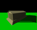
Now that you have the Mental Ray plug-in set up we are ready to start creating Bloom, you are going to need an scene full of objects in order to see the glow properly. I'm going to be showing you the effect on the objects I have labeled with red arrows so you know which ones I'm working on.
Step 1: Select Objects and Assign New Material

We are going to assign the Material Mia_Material_X to our objects, this material is located under Mental Ray.

 
Step 2: Edit Attribute Editor

Select Mia_Material_x in the attribute editor, and scroll down until you reach the Advanced Tab. Click the checkered box beside Additional Color, then scroll down to click textures under the Mental Ray section and select Mia_light_surface.
 
Step 3: Add Color

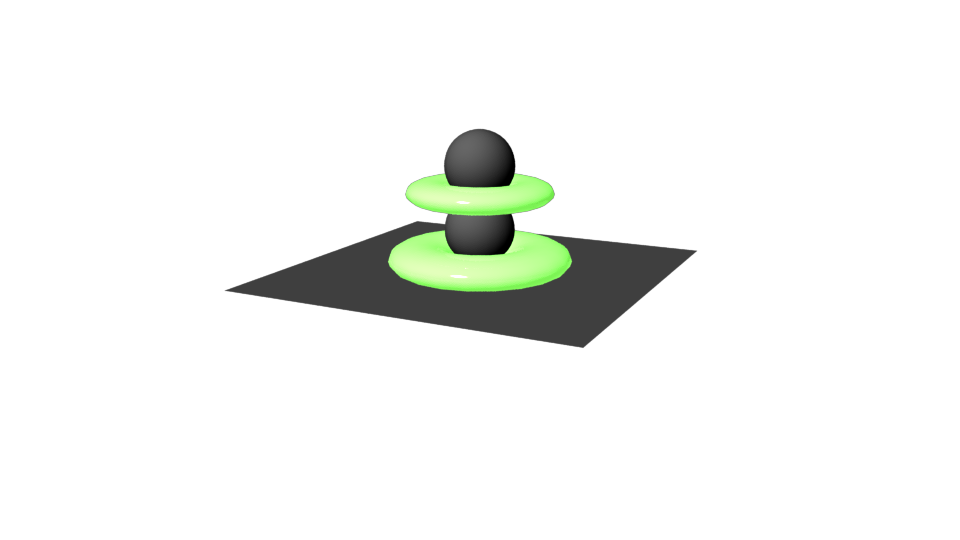
Now you are going to see an open tab called Mia_Light_Surface 1, in this tab you will see a option called Parameters. We are going to change the color to whatever color you want your glow to be, in this case I am going to make it green since its my favorite color.
Now to check that it worked, under the rendering window, render the current scene and ensure that you are rendering in Mental Ray (now this is just to check to make sure it worked.)


Step 4: Open and Adjust Render Settings

Under the render settings, in the Common tab you want to scroll all the way to the bottom to Render Options and turn off Enable Default Light.

Step 5: Turn on Final Gathering

Before closing the Render Settings, go across to the Indirect Lighting Tab and turn on Final Gathering.
Step 6: Edit Attributes

Going back to the Attribute Editor while Selecting your objects click the checkered Box beside additional color in the advanced tab, and you will see an option called fg Contib, this controls how much Final Gathering there will be. Increase this to a higher value such as 10 and edit the the intensity to about 0.9, which will give you a glow when you render.

Results: 

By playing around with these settings, you can achieve a interesting Bloom effect in Maya. You can also play around with the Final Gathering options Under the Indirect Lighting Tab in the Render Settings to give you a different effect.

BLOOM in GLSL

So my code is going to be using the glsl shader language, version 330 which has variables specific to my project so if it doesn't work for you don't worry you may just need to play around with a few things or rewrite it so it works with your project.

Now  in C++ code creating a Bloom effect involves numerous steps, the easiest way to remember what you need in order to create Bloom is to always refer to this diagram:

->This is essentially what steps are needed to create a Bloom effect in C++

       (1)               (2)              (3)                             (4)
 _______                                                             ______
|              |       ____          ____                          |            |
| scene    | --> |Tone| ---> |Blur| ----> ((+)) ---> |  YAY! |
|_______|       |____|        |____|            ^           |______|
    |             downsize    downsize          |              |
    |                                                                        |
    |____________________________________|

The first thing you need to do is render the scene you want to add Bloom to, you need to include both Your Vertex and Fragment shader. You will need to use a Pass Through Vertex shader which will look very similarly like this:

layout (location=0) in vec4 position;
layout (location=2) in vec3 normal;
layout (location=8) in vec2 texcoord;

uniform mat4 mvp;

out vertex
{
    vec3 positionObj;
    vec3 normalObj;
    vec2 texcoordObj;
} data;

void main()
{
    // mandatory!
    gl_Position = mvp * position;

    // additional info
    data.positionObj = position.xyz;
    data.normalObj = normal;
    data.texcoordObj = texcoord;
}

This shader will performs the clip transformation and passes all relevant attributes down the pipeline. The next shader you will need is your starting Fragment shader that applies both the lighting and the texture in the scene (Now if your project or engine already is applying lighting probably won't have to worry about it), which will look very similar to this:

in vertex
{
    vec3 positionObj;
    vec3 normalObj;
    vec2 texcoordObj;
} data;

uniform vec3 eyePos;
uniform vec3 lightPos;
uniform sampler2D diffuseTex;

layout (location=0) out vec4 fragColour;

vec3 PhongLighting(in vec3 fragPos, in vec3 fragNorm, in vec3 diffuseColour)
{
    // specular colour:
    // diffuse map provides diffuse colour... why not a specular map?
    // (it doesn't have to be white reflecting back at us)
    const vec3 specularColour = vec3(1.0);

    const float shininess = 10.0;

    // ...this is generally a dark constant
    const vec3 ambient = vec3(0.00, 0.00, 0.05);

    // diffuse component
    vec3 N = normalize(fragNorm);
    vec3 L = normalize(lightPos - fragPos);
    float Lambert = max(0.0, dot(L, N));

    // specular coefficient
    vec3 E = normalize(eyePos - fragPos);
    vec3 R = reflect(L, N);
    float Phong = max(0.0, dot(R, -E));
    Phong = pow(Phong, shininess);

    // add components
    vec3 diffuse = Lambert * diffuseColour;
    vec3 specular = Phong * specularColour;
    return ( diffuse + specular + ambient );
}

void main()
{
    vec3 diffuseColour = texture(diffuseTex, data.texcoordObj).rgb;

    fragColour.rgb = PhongLighting(data.positionObj, data.normalObj, diffuseColour);
}

The next step is to locate all the bright areas in scene which you need to use a Bright Pass/ Bright Tone fragment shader that will locate and isolate the bright areas of the scene. This fragment shader looks very similar to the following:

in vec2 passTexcoord;
uniform sampler2D sceneImg;
uniform float middleGrey;

layout (location=0) out vec4 fragColour;

float relativeLuminance (in vec3 rgb)
{
    return (0.2126*rgb.r + 0.7152*rgb.g + 0.0722*rgb.b);
}

vec3 brightPass(in sampler2D img, in vec2 uv, in float middle)
{
    vec3 colour = texture(img, uv).rgb; //makes image appear on screen
    float lum = relativeLuminance(colour);
    float bright = pow(lum, (middle/lum));

    return vec3(bright*colour);
}

void main()
{
    fragColour.rgb = brightPass(sceneImg, passTexcoord, middleGrey);
}

After finding the Bright Pass, you need to apply a Gaussian on top the bright Pass, I will be blurring the bright Areas with a Box Blur, however you will get a better result with a Gaussian Blur. In the Box Blur Fragment shader we are sampling from the image and creating the blur effect by using a Kernal Map. Another easy way to create the blur would to basically shrink the image down and then re-size it. The Box Blur Fragment shader will look very similar to the following:

in vec2 passTexcoord;

uniform sampler2D sceneImg;

uniform vec2 pixelSize;

layout (location=0) out vec4 fragColour;

//Box Blur
//You create a box blur using a Kernal map
vec3 boxBlur( in sampler2D img, in vec2 centerUV, in vec2 pixel)
{
    vec2 offsetUV;

    vec4 totalSample = 1.0*texture(img, centerUV);

    //bottom left
    offsetUV = -pixel;
    totalSample += 1.0*texture(img, centerUV+offsetUV);

    //optimization
    //we are going to weave through this Kernal

    //this is the Kernal we are sampling from
    // |1|1|1|
    // |1|1|1|
    // |1|1|1|

    //center bottom
    offsetUV.x = 0.0;
    totalSample += 1.0*texture(img, centerUV+offsetUV);

    //bottom right
    offsetUV.x = +pixel.x;
    totalSample += 1.0*texture(img, centerUV+offsetUV);

    //center right
    offsetUV.y = 0.0;
    totalSample += 1.0*texture(img, centerUV+offsetUV);

    //center left
    offsetUV.x = -pixel.x;
    totalSample += 1.0*texture(img, centerUV+offsetUV);

    //top left
    offsetUV.y = +pixel.y;
    totalSample += 1.0*texture(img, centerUV+offsetUV);

    //top center
    offsetUV.x =0.0;
    totalSample += 1.0*texture(img, centerUV+offsetUV);

    //top right
    offsetUV.x = +pixel.x;
    totalSample += 1.0*texture(img, centerUV+offsetUV);

    //average
    totalSample/= 9.0;

    return totalSample.rgb;
}

void main()
{
    //box blur
    fragColour.rgb = boxBlur(sceneImg, passTexcoord, pixelSize);
}

 Just like in Photoshop, just blurring the Bright Pass will not create an effective Bloom effect, you need to add it back to the original scene by screening it over the original Scene which will intensify the Bright Areas, creating a glow effect. To do this you need a Screen Composite Shader that will add the blurred bright areas back into the original scene, you can achieve this with 3 different methods, Blending the Image, creating a Multiply or screening the image which is the method I will be showing you. Your Screen Fragment Shader should look very similar to the following:

in vec2 passTexcoord;
uniform sampler2D sceneImg;
uniform sampler2D postProcImg;

layout (location=0) out vec4 fragColour;

//Screening
//This inverts the layers
//and multiples the result
vec3 screen(in sampler2D img0, in sampler2D img1, in vec2 uv)
{
    vec3 colour0 = texture(img0, uv).rgb;
    vec3 colour1 = texture(img1, uv).rgb;

    vec3 product = (1.0 - colour0) *(1.0 - colour1);

    return (1.0 - product);
}

void main()
{
    fragColour.rgb = screen(sceneImg, postProcImg, passTexcoord);
}


Results:

      Original With No Bloom                        Bloom Applied

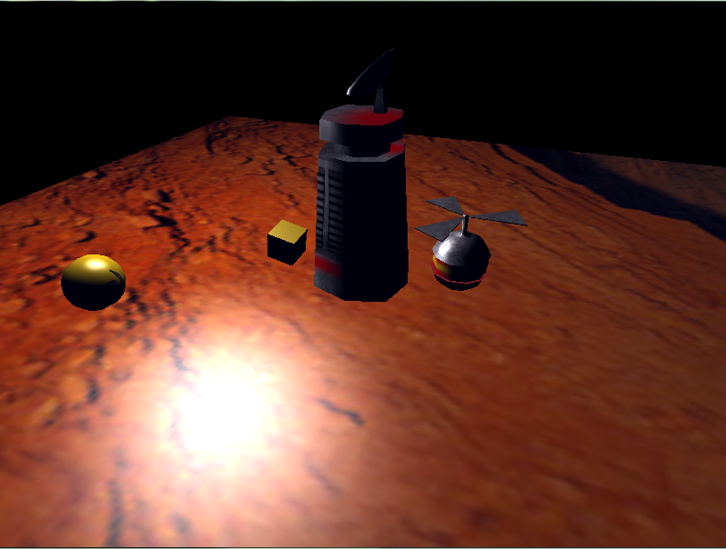
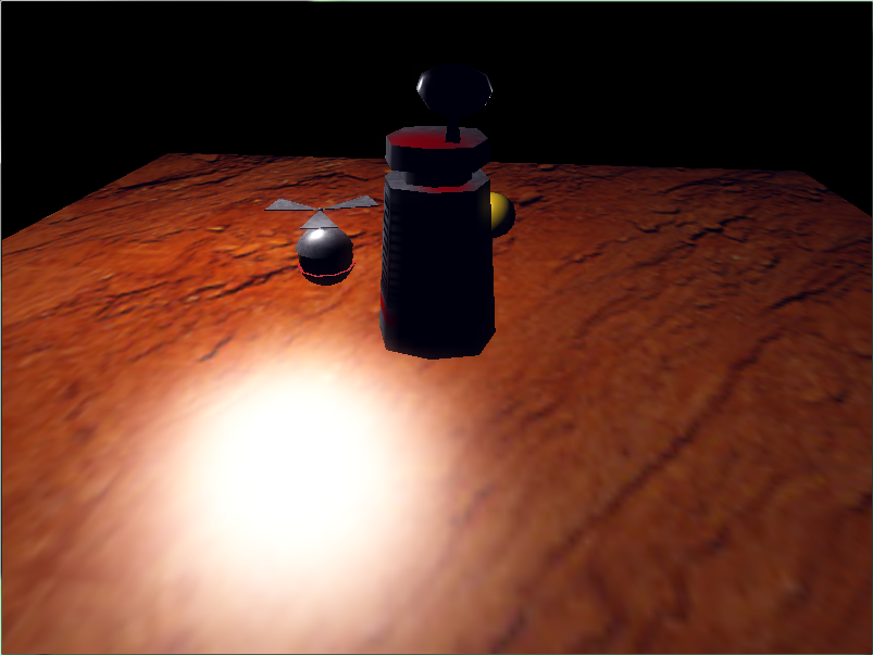
By following the correct steps you can create interesting and more realistic scenes using Bloom. Some Pro tips when creating Bloom in GLSL C++ shader language, use tone maps instead of numbers since it is easier to make bright areas brighter and takes less memory to do so. You can create the maps in Photoshop, which should be in grey scale with adjusted Luminance. By doing this you can easily create ton maps for your Bloom effect.

In addition, when using a Gaussian Blur for Bloom you need to remember that it takes into account more pixels and uses weighting. This weighting comes from Pascals Triangles, which an example to the 7th pass in the triangle is shown below:

  1
  1 1
 1 2 1
 1 3 3 1
 1 4 6 4 1
  1 5 10 10 5 1
  1 6 15 20 15 6 1

If you want a higher dynamic range in your Bloom effect try splitting up the post processing into multiple stages and repeat the Grabbing Bright Pass and Blurring steps, then add the original scene with all the iterations, which will not only give you a higher dynamic range but will also ease out the blurring and make your scene more realistic.